IoT101 Lesson1 Getting Started with ESP IoT Development
Getting Started with ESP IoT Development: Light Up Your First LED from Scratch
Many beginners want to build things like “remote PC power-on” or “smart home” systems. They stare at online tutorials for hours, only to be scared off by all the technical jargon. In reality, IoT isn’t that mysterious. Today, we’ll skip the fluff and explain everything in plain language—helping you truly understand microcontrollers and the ESP32, while also avoiding a few pitfalls I’ve personally stepped into.
1. What Exactly Is a Microcontroller?
You can think of it as a “stripped-down computer.” A computer has a CPU, memory, and storage. A microcontroller has those too—but to save power, reduce cost, and shrink size, everything is minimized to the extreme.
- Computer: Runs Windows, plays games, edits videos—but it’s expensive and power-hungry.
- Microcontroller: No desktop environment. It only runs the specific piece of code you upload. It can control when your rice cooker switches off or make a remote control emit infrared signals.
In one sentence: It’s a tiny brain that only does manual labor—and does exactly what you tell it to.
2. Why Does Everyone Recommend ESP?

There are many types of microcontrollers—like the old-school 8051 or the widely used STM32. But for IoT enthusiasts, the ESP series is the real sweet spot.
- ESP8266: The former king. Extremely cheap (just a few dollars) and comes with built-in WiFi. If you’re on a tight budget and don’t need fancy features, it’s still a solid choice.
- ESP32: The current mainstream option. Adds Bluetooth, dual-core CPU (faster), and more GPIO pins. Beginners are strongly advised to buy an ESP32 directly—don’t make your life harder just to save a few dollars with the 8266.
(Although I bought the 8266 because it was cheaper… but honestly, it’s still enough for now.)
3. The Beginner’s “Hardware Starter Pack”
To get started, you’ll need at least these three essentials:
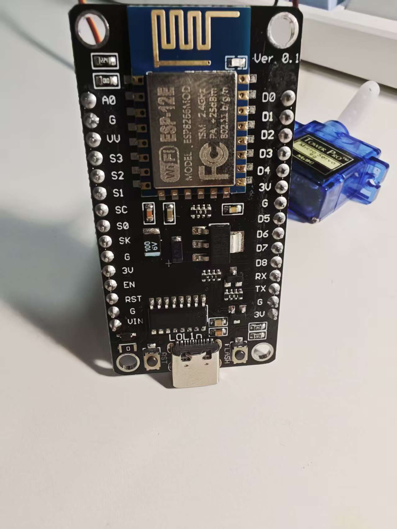
ESP Development Board: Don’t buy a bare chip (that requires soldering). Get one with a USB interface (like NodeMCU or the DevKit series). Just plug in a USB cable and you’re ready to program.
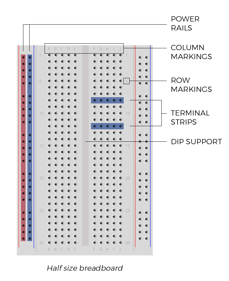
Breadboard: The middle area (where all the red and blue rows are connected) is internally wired together. You can plug in LEDs and wires without using a soldering iron. Perfect for those of us who hate hassle.
Jumper Wires: Those colorful little wires—male-to-male, male-to-female, female-to-female. Buy a pack of each. They’re cheap and very useful.
4. What Is GPIO? (Important! You Can Burn Your Chip!)
GPIO is basically the “tentacles” of the microcontroller. You can make it output voltage (to light up an LED), or read input signals (like detecting a button press).
⚠️ Pitfall Warning:
Most ESP32 pins use 3.3V logic levels. If you directly connect a 5V sensor without proper handling, you might literally see smoke and permanently damage your board. Be careful!
5. Let’s Get Hands-On: Light Up Your First Demo (ESP8266 Version)
We’ll make the built-in LED on the board blink. The main goal here is to complete the full workflow: code → compile → upload.
Step 1: Prepare the “Operating Table” (Arduino IDE Setup)
The ESP8266 isn’t officially part of Arduino’s core lineup, so we need to manually add support.
Download and Install:
Download the official Arduino IDE (choose version 2.x for a more modern interface).Add Board Manager URL:
- Open
File→Settings(Preferences). - In “Additional Board Manager URLs,” paste the following link:
http://arduino.esp8266.com/stable/package_esp8266com_index.json - Click OK to save.
- Open
Install Support Package:
- Click the “Board Manager” icon on the left sidebar (looks like a little drawer).
- Search for esp8266.
- Find the package developed by ESP8266 Community and click Install.
Tip: If the progress bar doesn’t move, it’s likely a network issue. Try using your phone’s hotspot or search for an “ESP8266 offline installation package.”
Step 2: Select the Correct “Identity”
After plugging the board into your computer, go to the dropdown menu at the top of Arduino IDE:
- Select Select Board → ESP8266 → NodeMCU 1.0 (ESP-12E Module) (this is the most common model).
- Select Port: Choose the one labeled with a
COMnumber (usually the highest number).
Step 3: Write the Code
Replace everything in the editor with the following code:
// On most ESP8266 boards (NodeMCU), the built-in LED is connected to pin D4 (GPIO2).
// Note: Many ESP8266 LEDs are “active low,” meaning LOW turns it on and HIGH turns it off.
void setup() {
  pinMode(LED_BUILTIN, OUTPUT); // Initialize built-in LED pin as output
}

void loop() {
  digitalWrite(LED_BUILTIN, LOW);  // Turn LED on
  delay(1000);                     // Wait 1 second
  digitalWrite(LED_BUILTIN, HIGH); // Turn LED off
  delay(1000);                     // Wait 1 second
}
Step 4: Upload
Click the “right arrow” icon in the top-left corner.
- Success: The bottom panel shows “Done uploading,” and you’ll see a small blue LED blinking.
- Error: If it says
Failed to connect, check whether your USB cable supports data transfer (some are charging-only). Try another cable. Also check if you need to install the CH340 driver.
6. Common Issues
- Driver Problems: If nothing happens after plugging in the board, you probably need a driver. Search for “CH340 driver” or “CP2102 driver.” They’re small (a few hundred KB). After installation, restart the IDE and the COM port should appear.
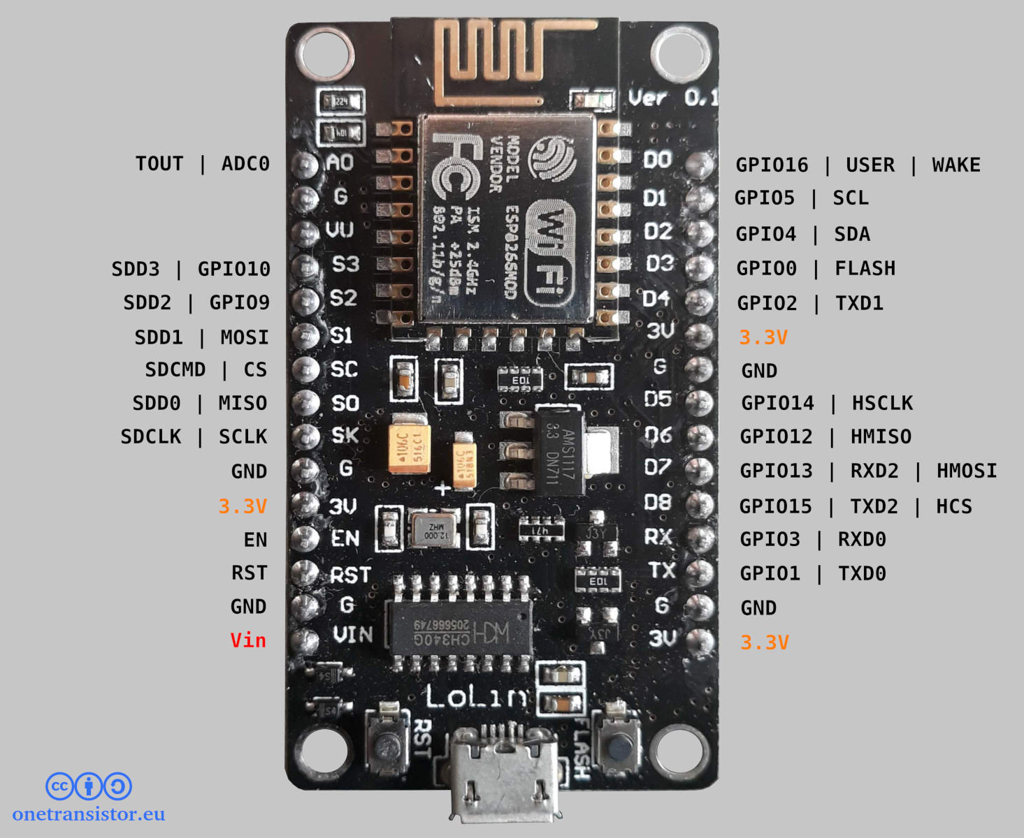
- Pin Mapping Confusion: The silk-screen labels on the 8266 board (like D1, D2) do not match the numbers used in code. For example,
2in code corresponds toD4on the board. Don’t force it—just check an “ESP8266 Pinout diagram” when in doubt. - What About WiFi? Since this is an IoT chip, not using WiFi would be a waste. In the next article, we’ll show you how to connect it to your home router with just a couple lines of code.
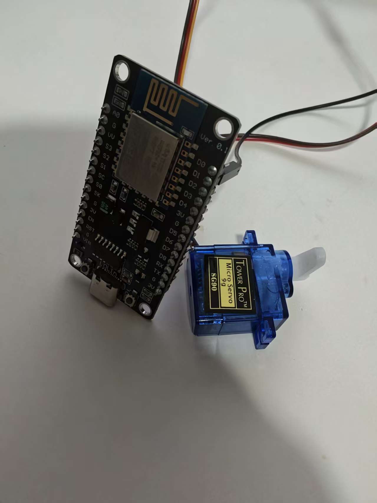
Next Preview: Now that the LED lights up, let’s do something cooler! Part 2: Hands-on “Finger Robot” — Use an ESP8266 to control a budget servo motor and physically press your computer’s power button or a light switch!